Technical Drawings
This section contains detailed technical drawings and diagrams for the FullShop Gen 3 system components. These drawings provide essential dimensional and installation information for system planning and setup.
Digital Feed Unit (DFU)
Section titled “Digital Feed Unit (DFU)”The Digital Feed Unit is a core component of the FullShop Gen 3 system. Below is the technical drawing showing key dimensions and specifications:
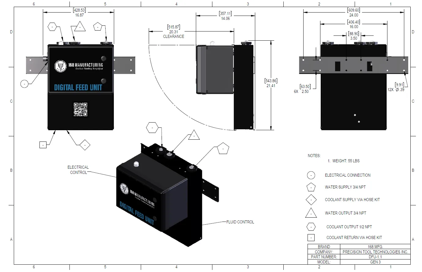
Key Features
Section titled “Key Features”- Precision-engineered housing
- Multiple connection points for system integration
- Industrial-grade construction
- Designed for optimal workflow integration
Installation Notes
Section titled “Installation Notes”- Refer to the Digital Feed Unit Installation Guide for detailed mounting instructions
- Ensure proper clearance around all sides for maintenance access
- Consider ventilation requirements when planning installation location
Sensor Valve Interface (SVI)
Section titled “Sensor Valve Interface (SVI)”The Sensor Valve Interface is a critical component that manages fluid control and sensor data in the FullShop Gen 3 system. Below is the technical drawing showing key dimensions and specifications:
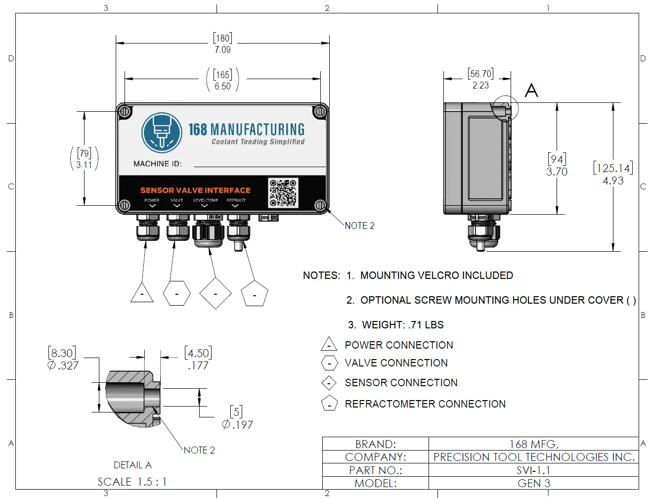
Key Features
Section titled “Key Features”- Integrated sensor connections
- Precision valve control system
- Industrial-grade enclosure
- Multiple mounting options
Installation Notes
Section titled “Installation Notes”- Refer to the SVI Installation Guide for detailed mounting instructions
- Ensure proper access to all connection points
- Consider cable routing when planning installation location
Mix Manifold
Section titled “Mix Manifold”The Mix Manifold handles the precise blending and distribution of coolant mixtures in the FullShop Gen 3 system. Below is the technical drawing showing key dimensions and specifications:
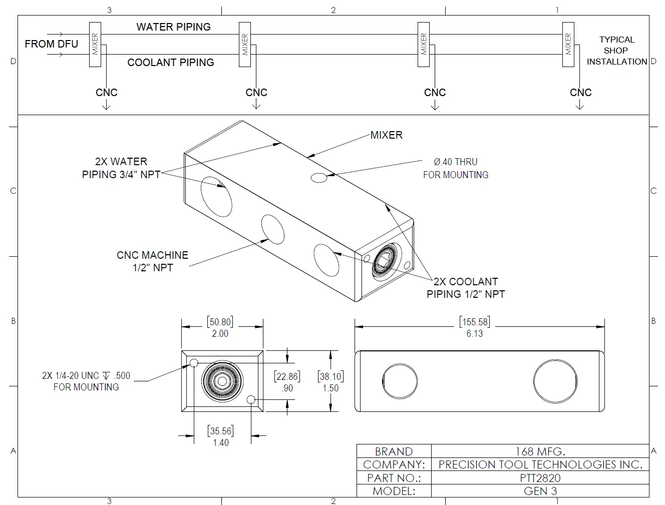
Key Features
Section titled “Key Features”- Multiple inlet/outlet ports
- Integrated mixing chamber
- Precision flow control
- Durable construction
Coolant Tote/Barrel Entry Adapter
Section titled “Coolant Tote/Barrel Entry Adapter”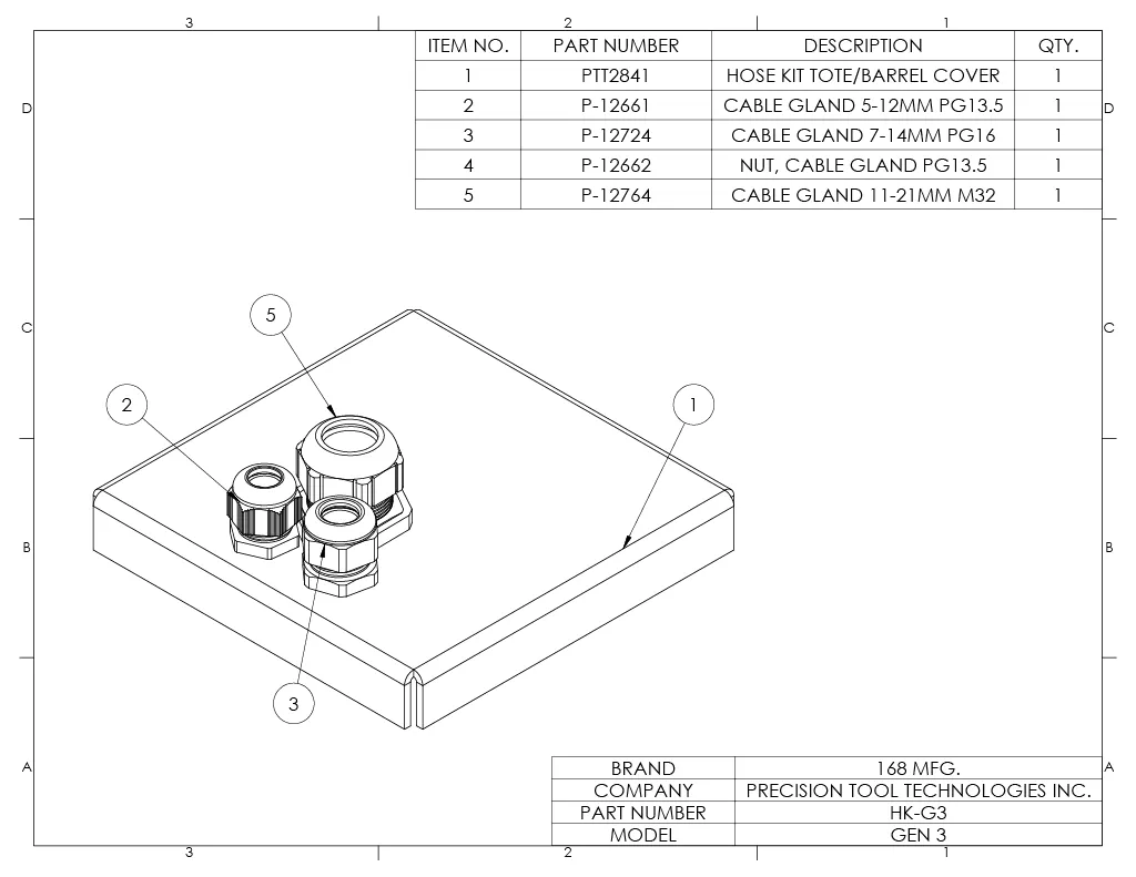
Insert hoses into glands
- Draw/Suction Hose into the gland labeled as item 5 on drawing
- Return/Relief hose into the gland labeled as item 3 on drawing
- Level Sensor into the gland labeled as item 2 on drawing. Finish by tightening glands in this order
- Tighten largest glaad first, smaller glands cap must be removed to tighten
- Tighten smaller glands last, larger glaand will need slight alightment to tighten
Additional Technical Drawings
Section titled “Additional Technical Drawings”Additional system component drawings will be added to this section, including:
- Bucket Fill Station
- System Layout Diagrams
Each drawing will include relevant dimensions, specifications, and installation notes to assist with system planning and implementation.