Digital Feed Unit (DFU)
The DFU has several connections: electrical, internet and fluids. For fluids this includes water supply, water out, coolant supply, and coolant out ports on the unit. View connection diagram
Physical Mounting
Section titled “Physical Mounting”Location Requirements
Section titled “Location Requirements”- Considerations for location in the building:
- Typically, a centralized location of your plant works well where the unit can reach the most CNCs in the least amount of plumbing
- Locate where a coolant source (barrel, tote, etc) is easily accessible and can be changed out
- Locate where services such as water, power, and internet are established or can be
Wall Mounting Guidelines
Section titled “Wall Mounting Guidelines”- Considerations for mounting on a wall:
- Physical size and mounting are documented in our drawing section of manual
- Position top of DFU about 6 feet high on wall. We have found this height range is the best overall for any maintenance or inspections needed. Do not mount too high for suction reasons.
- DFU weighs approx. 55 pounds, make sure your chosen mounting location can accommodate this
- Mount on wall with no or very low vibration
- Consider access for plumbing
- Instal customer supplied ball valves for the water supply, water output, and coolant output ports in case of quick shut off
Fluid Inlet and Outlet Connections
Section titled “Fluid Inlet and Outlet Connections”Refer to Infrastructure Plumbing, Overview Diagram and Digital Feed Unit
Connect Metalworking Fluid / Coolant Concentrate
Section titled “Connect Metalworking Fluid / Coolant Concentrate”- Components provided in kit for - View Kit
- Connect DFU to barrle or tote with hose kit and adapters provided in your shipment.
- Inlet: Connect to fresh coolant
- Return: Return non-mixed fluids to tank. For relief pressure if ever required.
Electrical Supply
Section titled “Electrical Supply”- 120VAC/15amp source required to power Digital Feed Unit
- DFU uses and IEC style receptacle if you want to source longer cable
Level Sensor - Monitors coolant supply
Section titled “Level Sensor - Monitors coolant supply”- Components provided in kit - View Kit
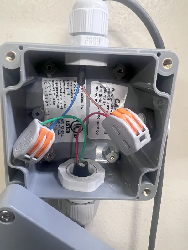
- JUNCTION BOX WIRING:
- Insert Level Sensor cable into grey junction box if it is not already assembled
- Insert flying lead end of M12 cable (one orange end) - terminate to desired length
- Use provided WAGO connectors to wire per below:
- Level Sensor Red wire to >>> BROWN wire on M12 cable
- Level Sensor Green wire >>> BLUE wire in M12 cable
- Yellow wire NOT USED
- Mount Terminal Box in desired location - and router wire convenient for uses
Internet Connection
Section titled “Internet Connection”- An internet connection is required for the services below to work as intended
- Remote service and troubleshooting
- Machine configuration and operation
- Timely alaerting for warning and faults
- Reports as subscribed (consumption/insight/etc.)
- Uses TSL technology and industry standard encryption technology ensures your data stays protected in transit for complete IoT security.
- Call us if your IT staff has any concerns, we have taken extra steps with external IT consultants to ensure this is a safe and low risk solution.