Bucket Fill Station Installation
This guide covers the installation and setup process for the Bucket Fill Station, including mounting requirements, plumbing connections, and electrical connections.
A BFS kit is provided with each DFU (See BFS) so you can manually dispense coolant where this kit is installed. The kit includes the following: Mix Manifold, Sensor Valve Interface, Fluid Fill Valve, Activation Button with wire and mounting Velcro. See details on Sensor Valve Interface for installation – the below connection will be made. SVI Installation
If you do get alarms for your bucket fill station, here is how to clear them.
- Connect a level – temp sensor to the bucket fill SVI.
- Use a bucket or container and fill about 50% of it with water.
- Parameterize the bucket or container in the 168 app so the level alarms and warnings can be cleared.
- Drop sensor in bucket or container and wait until the alarms state “previous” and can be cleared.
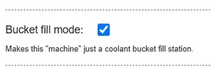
- Once all alarms are cleared, change SVI back to “Bucket fill mode” in machine setup.
- Unwire the level – temp sensor from the bucket fill SVI.
Electrical Supply
Section titled “Electrical Supply”- 120 VAC source required to power Sensor Valve Interfaces at each CNC. Use Black cable with Red and Black conductors. Wire to + / - of 120 VAC adapter and SVI.
Fluid Fill Valve
Section titled “Fluid Fill Valve”- Valve cable is 2-meter long with flying lead and can be terminated in the field to preferred length.
- Secure cables in a manner that will keep them where you intend.
- Typically installed around chest height and secured via piping clamps.
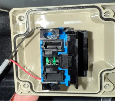
Activation Button
Section titled “Activation Button”- Grey terminal box with GREEN push button. Wire button to + and D to left of IDENTITY switch as shown below. Terminal provided cable to desired length and mount box.