Sensor Valve Interface Installation
This guide covers the installation and connection procedures for the Sensor Valve Interface (SVI), including mounting specifications, wiring diagrams, and connection details.
A kit for each CNC is provided and includes the following: Sensor Valve Interface, Temp/Level Sensor, Fluid Fill Valve and mounting Velcro. SVI Kit
The SVI (Sensor Valve Interface) is small wireless device mounted at each CNC. Its electrical input and outputs are used for auto filling. To view SVI dimensions please see drawing section or visit www.168mfg.com.
Electrical Supply
Section titled “Electrical Supply”- 120 VAC source required to power Sensor Valve Interfaces at each CNC.
- Make sure an outlet is withing 15 feet of Sensor Valve Interface
- AC/DC wall mount power adapter provided in kit (24 VDC)
Enclosure Mounting
Section titled “Enclosure Mounting”- Mount as high as possible, noting the level/temp sensor cable is 2 meter long.
- We recommend using the provided Velcro (hook and loop). Spot clean before you adhere to CNC
- If preferred, mount it via screws using holes under the SVI cover.
Level and Temperature Sensor
Section titled “Level and Temperature Sensor”- Sensor cable is 2-meter long, installing sensor near the OEM sight tube works well.
- It is often best to install sensors in the deepest part of the sump.
- Sensor foot mount needs to be on bottom of the sump as it holds the sensor vertically and at correct bottom.
- 3” diameter opening required with mounting foot or 1.25” with foot unthreaded.
- Secure cables in a manner that will keep this where you intend.
Fluid Fill Valve
Section titled “Fluid Fill Valve”- Valve cable is 2-meter long with flying lead and can be terminated in field to preferred length.
- Secure cables in a manner that will keep them where you intend.
- Typically installed around chest height and secured via piping clamps
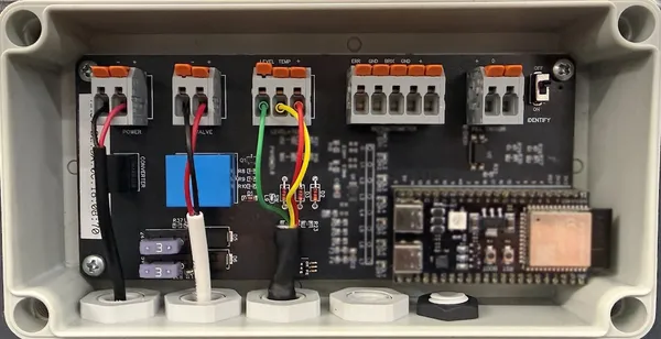
Wiring Devices to SVI
Section titled “Wiring Devices to SVI”To begin, remove cover and insert device wires into gland as indicated on front label – making sure to tighten glands when finished.
- Power: 2 wire connection from AC/DC power supply. Use Black cable with Red and Black conductors.
- Black wire to – terminal
- Red wire to + terminal
Valve: 2 wire connection from valve cable - terminate at preferred length
- Black wire to – terminal
- Red wire to + terminal
Temp / Level Sensor: 3 wire connection from sensor cable
- Red wire to + terminal
- Yellow wire to Temp terminal
- Green wire to Level terminal
Standard SVI Wiring
Inline Refractometers (Concentration/Brix Sensors)
Section titled “Inline Refractometers (Concentration/Brix Sensors)”The FullShop™ Gen3 series will in the future support select inline refractometers with 4-20 mA outputs for CBS mode. These sensors provide automated brix measurements as well as any errors or alarms the refractometer may have.
- Contact support to request supplementary install guide
- Terminals used are: ERR, GND, BRIX, GND and +