System Startup
Initial Checks
Section titled “Initial Checks”Before proceeding with system startup, ensure all plumbing and wiring is complete. Verify the following:
- E-Stop is pushed in
- DFU is connected to 120V circuit
- Circuit breakers inside unit are on
- Allow 30-60 seconds for system boot up when powered on
- Scan QR code on unit to access the FullShop app
High-Level Startup Sequence
Section titled “High-Level Startup Sequence”%%{init: {'theme': 'base', 'themeVariables': { 'primaryColor': '#ffffff', 'primaryTextColor': '#1c6b92', 'lineColor': '#6d6e71', 'secondaryColor': '#8eaec9', 'tertiaryColor': '#c64527'}}}%%
graph TD
A([Start]) --> B
B[Confirm Plumbing & Wiring]
B --> C[Power Up DFU]
C --> D[Connect DFU to Wi-Fi]
D --> E[Power Up SVI]
E --> F[Add SVIs to Mesh Network]
F --> G[Bleed Water Header]
G --> H[Bleed Coolant Header]
H --> I[Setup SVIs in App]
I --> J[Validate at each CNC]
J --> K([System Ready])
style A fill:#1c6b92,stroke:#1c6b92,color:#ffffff
style B fill:#ffffff,stroke:#1c6b92,color:#1c6b92
style C fill:#ffffff,stroke:#1c6b92,color:#1c6b92
style D fill:#ffffff,stroke:#1c6b92,color:#1c6b92
style E fill:#ffffff,stroke:#1c6b92,color:#1c6b92
style F fill:#ffffff,stroke:#1c6b92,color:#1c6b92
style G fill:#ffffff,stroke:#1c6b92,color:#1c6b92
style H fill:#ffffff,stroke:#1c6b92,color:#1c6b92
style I fill:#ffffff,stroke:#1c6b92,color:#1c6b92
style J fill:#ffffff,stroke:#1c6b92,color:#1c6b92
style K fill:#1c6b92,stroke:#1c6b92,color:#ffffff
Detailed Process Steps
Section titled “Detailed Process Steps”1. Confirm Plumbing & Device Wiring
Section titled “1. Confirm Plumbing & Device Wiring”- Has plumbing professional double checked and proofed the work? Confirmed & Signed Off
- Has electrical professional double checked and proofed their work? Confirm & Signed Off
2. DFU Power Up and Wi-Fi Connection
Section titled “2. DFU Power Up and Wi-Fi Connection”Power Setup
Section titled “Power Setup”- Before plugging in, confirm DFU Mesh physical address switches are as intended. View switch settings
- Turn ON 3-AMP breaker > Turn OFF 10-AMP breaker
- Plug in to 120V, this will power your device
USB Cable Connection
Section titled “USB Cable Connection”- With DFU electrical enclosure opened
- Locate the control board on backside of door
- Locate USB-C connectors lower left corner of the control board
- Plug USB-C cable into left most connector
- Plug USB cable into PC running Google Chrome
- Proceed to App to configure SSID and password
App Configuration
Section titled “App Configuration”- Using app: Settings > DFU setup > Select DFU > Name DFU > Parameterize DFU > Save
- Using USB cable, connect DFU to PC with Google Chrome. Use left-most USB-C port inside DFU electrical enclosure
Wi-Fi Setup
Section titled “Wi-Fi Setup”- Using app: Settings > DFU setup > Select DFU > Configure DFU Wi-Fi > follow instructions
- While proceeding, confirm the Wi-Fi to DFU is established. 3 ways to confirm:
- External LED will go from white to blue
- Internal string LED labeled L2 will be blue
- App shows sync status via icon at upper right corner. May require refresh.
3. SVI Power Up
Section titled “3. SVI Power Up”- Before plugging in, confirm SVI Mesh physical address switches match as intended. View switch settings
- Before plugging in, confirm IDENTITY Switch is OFF (pushed up).
- Leave covers off for future steps.
- Plug in 120 V adapter to power device.
4. Add all SVI ‘s to mesh network with app
Section titled “4. Add all SVI ‘s to mesh network with app”- Using app: Settings > DFU Setup > Select DFU > Use CLICK TO ADD to add all Unrecognized SVIs
5. Water Header: Bleed Trapped Air
Section titled “5. Water Header: Bleed Trapped Air”- Turn ON 10-AMP breaker
- Close door to DFU
- Clear all DFU errors. Bleeding will not work with fill prevention alarms presisting
- Enable DFU in software
- BEFORE PROCEEDING make sure ALL ID switches are in off position - any left on will flow water.
- START WATER FLOW: Using the app: DFU Details > Select DFU > DFU Settings > Bleed out Air > Move Water Bleed selection to “Water Flowing”. Confirm pressure is being made using water pressure gauge.
- Physically go to each SVI and use IDENTITY switch to open fill valve. Once water is flowing and air looks bled out close valve with IDENTITY switch.
- If you installed an additional manual bleed out valves, open / close to bleed any remaining trapped air.
- STOP WATER FLOW: Using the app: DFU Details > Select DFU > DFU Settings > Bleed out Air > Move Water Bleed selection to “Standby” - CONFIRM WATER PRESSURE IS DROPPED BEFORE PROCEEDING
6. Coolant Header: Bleed Trapped Air
Section titled “6. Coolant Header: Bleed Trapped Air”- Turn ON 10-AMP breaker and clear any DFU errors.
- Physically go to closest manual bleed out valve, open to allow air escape. Bring container or hose to catch any oil that escapes from bleeding process.
- START COOLANT FLOW: Using app: DFU Details > Select DFU > DFU Settings > Bleed out Air > Move Coolant Bleed selection to “Pump Coolant” Initial speed setting is 1% - slow increase flow. No need to rush as pipes typically fill quickly. Confirm pressure is being made using coolant pressure gauge.
- Once coolant is flowing and air looks bled out close manual bleed valve while quickly proceeding to next step.
- STOP COOLANT FLOW: Using app: DFU Details > Select DFU > DFU Settings > Bleed out Air > Move Coolant Bleed selection to “Standby”
- Proceed to next closets bleed valve and repeat above steps at EVERY location where trapped air could be.
- When finished at all bleed locations
- CONFIRM in app that both Coolant bleed and Water bleed are in Standby
- CONFIRM COOLANT PRESSURE IS DROPPED BEFORE PROCEEDING
7. Setup each SVI with app
Section titled “7. Setup each SVI with app”- Physically go to first CNC machine – turn IDENTITY switch to ON position (down)
- Using app: Settings > Machine Setup > Select Machine > Select REGISTER NEW MACHINE at top of list
- Name machine as you refer to it in the shop (example Mill 43, DMG-Mori #4, ect.)
- Select DFU this SVI pairs with. Many shops only have a single DFU.
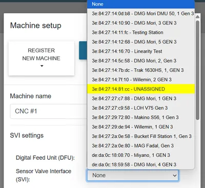
- Select the highlighted SVI and confirm MAC address on PCB (see below example)
- Using app: Complete required entries and selections when completed click REGISTER NEXT at top of page.
- At this CNC machine turn IDENTITY switch to OFF position (up)
- Repeat above step at each CNC until all SVIs are in the app paired to correct DFU.
- Use SAVE at top of app and return to summary page, review to confirm machines appear as expected.
- When finished – all SVI should be disabled and ready to validate.
- Reset any alarms that may have triggered at power up – may require 2 attempts to clear at first power up.
8. Validate at each CNC
Section titled “8. Validate at each CNC”- Physically go to first CNC. Double check IDENTITY switch is OFF (up position).
- Pull Level Sensor from Sump to purposely trigger low warning and low alarm – confirming wiring and sensor.
- Reset level sensor alarms that triggered. May require 2 attempts to clear at first power up.
- Repeat at all other CNC on the application.