
Piping and Tubing
This guide covers the installation and setup of the base plumbing infrastructure required for the FullShop Gen 3 system, including pipe specifications, layout requirements, and connection points. 168 MFG prefers to review site plan with clients to review pressure drop in anticipated materials and lenghts.
Our experience is that the quality of the installation is proportional to the quality of the project management and planning that goes into it. Provide clear directions and instructions for your plumbing crew. Clear communication on where pipe runs, and drop are expected to be installed go a long way to customer satisfaction.
Concepts and Sizing
Section titled “Concepts and Sizing”There are two main piping concepts used to install a FullShop Gen 3 solution – See also Best Practices
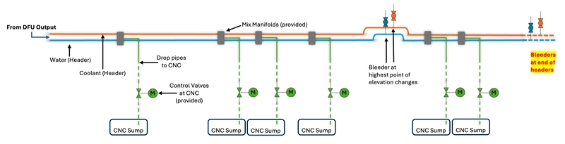
- Header pipes installed from DFU into plant.
- Pipe 1: Water Size is typically 1” or 1 ¼”.
- Pipe 2: Coolant Size is typically ¾” or 1”
- Branches runs in headers are acceptable
- Loops runs in headers are acceptable but but not typical or required
- Drops from Mix Manifold to CNC for emulsion.
- ½” through ¾” are common sizes.
- Each CNC machine requires its own mixing manifold which is provided in the kit.
For water header piping the objective is:
Section titled “For water header piping the objective is:”- To specify pipe diameters, that once plumbed the system flow is 4 gallons per minute (GPM) with customers supplied water pressure. For convenience the below reference table shows estimated pressure drop for common sizes and lengths and adds +25% for fittings.
For coolant header piping the objective is:
Section titled “For coolant header piping the objective is:”- To specify pipe diameters, that once plumbed using customers supplied coolant at max flow of 0.8gpm, system pressure is appropriate for materials used. Working pressure of customers supplied piping and coolant viscosity need to be considered. Note that the DFU internal relief is 145psi.
Estimated Values for Water and Emulsion at 4 GPM
Section titled “Estimated Values for Water and Emulsion at 4 GPM”| Type | PEX tube diameter (in) | 1 psi loss (ft) | 5 psi loss (ft) | 10 psi loss (ft) | Gallons per 100 feet (gal) |
|---|---|---|---|---|---|
| Drop | ½ | 4 | 21 | 43 | 0.92 |
| Drop | ⅝ | 11 | 53 | 106 | 1.60 |
| Drop | ¾ | 22 | 111 | 222 | 1.83 |
| Header | 1 | 75 | 380 | 760 | 3.03 |
| Header | 1 ¼ | 200 | 975 | 1950 | 4.60 |
Drops from Mix Manifold to CNC Sumps
Section titled “Drops from Mix Manifold to CNC Sumps”- Consider a location near site tubes. These are ideal in many cases.
- If the above is not possible consider where you manually fill.
- When a larger external tank is present this location may work if this is where coolant depletes.
- Fill into filtered side of tank when possible.
Best Practices
Section titled “Best Practices”- PVC or PEX tubing are most common materials used. With PEX full flow fittings are preffered
- Our recommendation is DO NOT use brass fitting on the coolant lines or where you have RO/DI water.
- Changes in elevation that could trap air REQUIRE bleeder installation.
- Shut offs at supply and pump system are suggested for service reasons.
- Better emulsification occurs with ambient temperature water and coolant. Think about your pipe routing, refills and overall volume, which may require additional water tempering.
- Our water flowmeter requires users to provide filtering. Particles must not exceed 0.50mm
- Before connecting water source flush pipes carefully to avoid blocking the water turbine caused by particles from the pipe installation.
- Please review notes about water hardness in Technical Data.